
Gnd

Power Consumption
Scanning mode
70 mA
Duration 30 secs --- typical response time
Display mode
90 mA
Continuous
SDI-12 mode
20 mA
Continuous while waiting for commands
RS4-85 mode
20 mA
Continuous while waiting for commands
Analogue output mode
25 mA
Continuous


Further Information
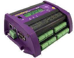
The DT80 logger and VibWire-108 can be seamlessly integrated to form a flexible stand-alone Geotechnical logger unit with USB data storage capability and all the facilities available from the DT80. The VibWire-108 contains all necessary protection circuitry to enable the system to be directly deployed for remote field applications. Low power operations can be optimised under program control within the DT80 software operations.
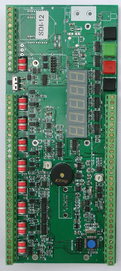
SDI-12
Scan Time
The VibWire-108-SDI12 takes approximately 30 seconds to complete the scan for 8 channels and this reduces to 16 seconds for 2 vibrating wire sensor inputs. However this delay is dependent upon the operating frequency of the sensors being used. The lower the vibrating wire sensor frequency then the longer it takes to determine the result. Analogue input signals are measured instantaneously and as such are not considered to cause a delay within the measurement cycle.
Lightening Protection
The VibWire can be fitted with both gas discharge tube and transorb lightening protection so ensuring that the instrument will operate as safely as possible under the effects of local ground strikes.
DT80
The advanced power management built into the VibWire-108 range enables the instruments to be deployed using Solar cells for many applications.
Fig 2 - Direct Connection to DT80
Fig 3 shows how the VibWire-108 connected to the SDI-12 ports on the DT80. Any SDI-12 port on the DT80 can be used so long as defined within software.
PCB Jumper Settings
Jumper Open = 0-2.5V DC
4-20 mA loop
Jumper Closed = Thermistor
Operations
The VibWire-108 will operate within its factory default settings with ID = 0, and the output set to SDI-12 mode. The instrument also remembers its configuration and can be left in its preset state ready to operate immediately upon power on.
The relay within the DT80 is ideally suited to control power to the VibWire-108 and can be used to switch the instrument off between readings.
After applying power the DT80 can then instruct the VibWire-108 to make a measurement and read then sensor values. Once the new sensor information is read the VibWire-108 can be powered off.
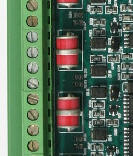
PCB Jumpers
Fig 3
Direct Connection to DT80 Logger
The simplest way to use the VibWire-108 and DT80 together is connect the two instruments together using the SDI-12 port for communications and to power the VibWire-108 from the same source as the DT80.
The VibWire-108 only requires approximately 70 mA at 12V DC at its peek level when operating in SDI-12 mode. A small solar panel with battery backup is all needed to deploy the VibWire-108 for unlimited stand-alone operations in most applications.
The simplest way to use the VibWire-
The VibWire-
All of the VibWire-108 models support thermistor, analogue input for the range 0 - 2.5 V DC and current loop inputs. For current loop operations such as those 0- 20 mA, 4- 20 mA then external excitation is required.