
|
AD2416VFATM 16 Channel Voltage Input Module |
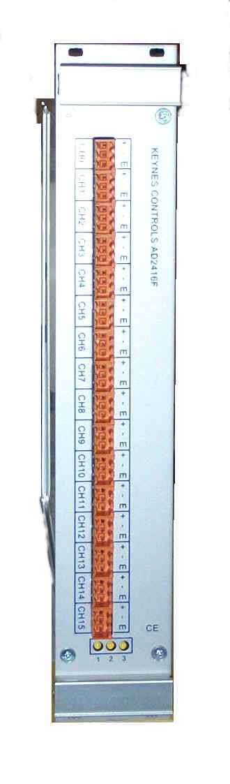 |
IntroductionThe AD2416VF module is a simultaneously sampling 16 channel 24 bit Sigma Delta ADC module designed to communicate to the Keynes SONET node part number KC5000-SonetATM. Using a high speed RS-422 serial interface the SonetATM node is used to convert the AD2416VF digital packets into a format which can be sent down an ATM network. The AD2416VF module can also communicate directly to a data logger PC running a Windows operating system via an RS-422 interface card. In order to enable the AD2416F device to be as flexible as possible, the electronics is divided into two separate modules. The first module consists of the analogue signal conditioning and the second boards is the digitisation unit. Splitting the unit into two sections means that the unit can be easily customised if required to suit most signal conditioning by simply removing the signal conditioning card and replacing it with a new unit. Data SynchronisationThe AD2416VF contains 8 x stereo 24 bit Sigma Delta converters for the digitisation of the analogue signals. Each converter is absolutely synchronised with all other converters within the unit and across the network. The AD2416VF modules operate in a Master/Slave mode of operation. The first card in the system always acts as the master and as such provides the timing and synchronisation data to the rest of the systems. There are no differences in the way the master and slave cards are constructed. The master card is determined solely upon the units location within the rack. Boot Sequence & SynchronisationUpon initialisation the Master card sends out an initial boot sync signal of duration around 5 seconds. Upon receiving the boot sync signal the slave cards synchronise to the clock signal being sent out by the master card. After receiving the boot sync signal all future data acquisition synchronisation is carried from the timing signal sent to all slave cards by the master card. |
Specification |
ADC Channel Schematic |
|||
| Number Channels | 16 Full Differential |
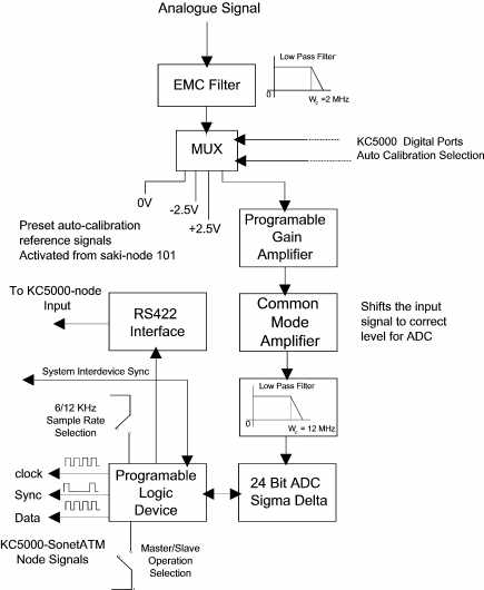 Figure 2 Figure 2
|
||
| ADC Type | Stereo 24 Bit Sigma Delta
Crystal CS5396 |
|||
| Dynamic Range | > 100 db | |||
| Sample Rate | 6 - 12 KHz/Chan Switch selectable |
|||
| Input Impedance | > 10 MW | |||
| Operating Temp °C | -10 to 50 °C | |||
| Storage Temperature | - 20 to 60 °C | |||
| Calibration Type | Auto-calibration by precision
DC reference Global across all channels |
|||
| Calibration Points | 3 point calibration -2.5V, 0V and +2.5V Selectable by KC5000 -SonetATM node digital I/O | |||
| Calibration Temp Sensitivity | 5 ppm/°C each range. | |||
| Comms. Port | RS422 Serial port Max transmission length = 10m 6 Mbaud @ 12KHz/channel |
|||
| Power Supply | 12 - 24V Auto-detect @ 15W | |||
| Status LED | 1 = Power 2 = Bootup |
|||
| Height
Width Depth |
262 mm 45 mm 220 mm |
|
The Electronics for the AD2416VF module is provided in two separate parts, the analogue inputs and the network interface. Figure 3 shows the analogue input module. Figure 4 shows the RS422 network interface. The unit is supplied electrically in two parts in order that Keynes Controls can customise signal conditioning should this be required by clients without having to construct complete circuit boards. It is a simple matter to remove and replace the analogue front end module in the field if required. |
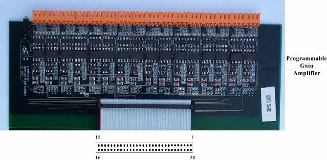 Figure 3 |
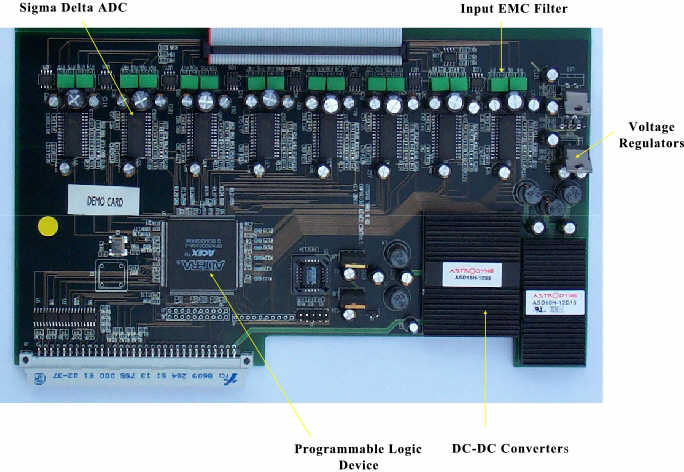 Figure 4 |
Synchronisation & Timing SignalsFigure 5 shows the timing and synchronisation signals generated and used by the AD2416VF unit to ensure synchronisation. A single AD2416F unit is set-up as the master and all other units are configured as slaves. The Master card generates the clocks signals from using a precision crystal oscillator and passes this signal via a daisy chain to all other slave cards |
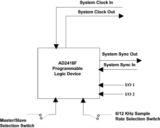 Figure 5 |
|
There are no physical differences in the circuit boards configured as a master units to those configured as a slave units. The AD2416VF card that acts as the master has a high logic level applied to the pin on the programmable logic device used to select the mode of operation. The Master/Slave switch is set high to make the AD2416F unit run as a master and low to run as a slave. The selection is physically made by voltage level supplied from the backplane and for this reason card 1 is always the master. (See Figure 6) It is possible to swap around cards in the rack and for any other card to be used as the master. There are no additional changes to be undertaken when swapping the cards other than powering off the system and allowing it to restart with the cards in their new places. |
As can be seen in Figure 6, the synchronisation and clock signals are daisy chained to each module in turn. The daisy chaining of signals from module to module is carried out to ensure that the timing signals do not get affected by noise or distortion across the back plane and has the affect of removing any chance of false triggering due to false misinterpretation of the timing information. Sample Rate SelectionA switch mounted on the front panel of the rack (See Figure 5) is used to physically alter the sample of the system from 6 to 12 KHz. The sample rate adjustment is achieved by simply dividing the data clock signal by 2. The clock signal generated by the master is passed to each slave unit and so divides the sample rate on these cards simultaneously to the adjustment on the master. The AD2416VF card gathers data at fixed sample rates. The software driver is used to provide different data rates by data decimation where required. |
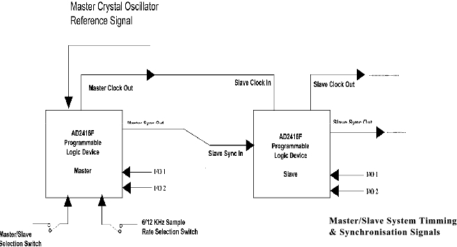 Figure 6 |
|
Figure 7 shows how the AD2416VF card is integrated into a fully synchronised ATM data acquisition network. The ATM switch shown can in fact be any manufacturers switch and any number of ports and user data loggers can be installed. All instruments connected together using the ATM switch will be synchronised no matter how the network is distributed. |
