|
À |
Built-in bridge signal conditioning for 120, 350,500 and 1KW strain gauges. |
|
|
|
À |
Stable, accurate, low-noise signal conditioning. |
|
À |
Voltage and constant current bridge excitations. |
|
À |
1/4, 1/2 and full bridge operations. |
|
À |
Software programmable gauge factor. |
|
Both the 16-and 24-bit strain gauge interfaces are sensitive enough to monitor strain signals in many applications without any need for signal amplification. Use of this module ensures the highest possible signal-to-noise ratio for any strain measurement. Table 2 summarises the operating specifications of the strain gauge interfaces. |
|
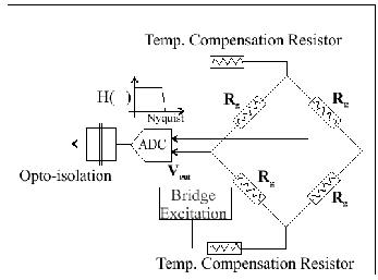
The circuit schematic shown in Fig 16 is common for both load cell and strain gauge sensors. |
|
Sensor Interfaces |
|
Full Bridge - Temperature Compensated Strain Interface Fig 16 |
|
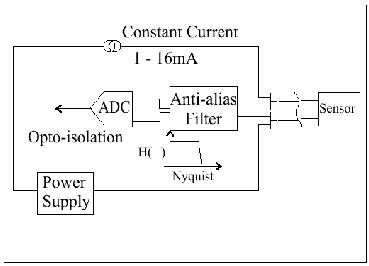
A series of interfaces are provided to drive and read signals from the 2 wire ICP accelerometers. The constant current operations provide a simple, compact, noise immune procedure for measuring acceleration using industry standard sensors. Each interface provides the following features: |
|
|
|
À |
Integral ICP interface. 24 V @ 1-16mA |
|
(Constant Current). |
|
|
|
À |
Sample rate following anti-alias filters. |
|
|
|
À |
Sample rates 0.1-78 KHz. |
|
|
|
À |
16 & 24 bit ADC resolution. |
|
|
|
À |
Individual ADC per channel |
|
|
|
À |
Opto-isolation to 1000V DC |
|
ICP Accelerometer Interface |
|
Part Number NP24AI-V1H1, NPAI16-V78K & -NP4501-ACL Fig 17 |
|
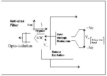
Each analogue module contains the following features: |
|
À |
Individual ADC per channel. |
|
|
|
À |
Opto-isolation for improved common mode operations. |
|
|
|
À |
Over-voltage & short circuit protection. |
|
|
|
À |
Sample rates from 0.1-78 KHz/Channel. |
|
|
|
À |
Sample rate following anti-alias filter and pre-amplifier gain. |
|
|
|
À |
16-bit & 24-bit ADC Resolution. |
|
|
|
Each analogue input module utilises low noise electronics to ensure that the input signal. measured with the highest possible accuracy. An EEPROM is installed on each interface to store manufacturing, calibration and setup details. No configuration information is lost, even when the systems are powered off. |
|
Voltage Input Interface |
|
For the NetPod 4000 Series Instruments |
|
12 |