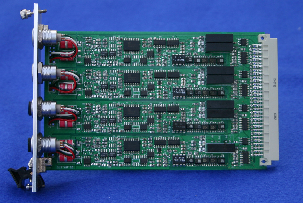
Analogue Input Cards
All of the analogue cards contain are supplied on the same quick mount chassis for installation and removal. The cards simply push into the rack and are secured with the mounting screws. It takes only a matter few seconds to insert and secure a card.
The analogue cards all support 4 input channels and containing digital anti-ailiasing filters, individual ADC, signal conditioning where appropriate and options for lightening protection or opto-isolation to 1000V DC.
Analogue input support for Voltage, Thermocouple, RTD, Current loop, Piezo-electric, Resistance, Thermostor are available.


1
2
3
1. V1H1
1 : S (+)
2 : S (-)
3 : V (+ 12V)
4 : GND (COM)
5 : V (- 12V)
2. SC1
1 : S (+)
2 : S (-)
3 : REF
4 : GND (COM)
NetPod 4003 Analogue Card Pin-outs
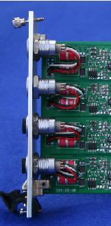
Surge/Lightening Protection
Each of the input cards has option to fit opto-isolation or lightening/Surge protection depending upon the environment into which the instrument is to operate.
Lightening/Surge protection is undertaken by Gas Discharge tube and transorbs. Any surge caused by local lightening strikes etc. is discharged to ground and so protects the instrument electronics. The protection survives 20,000 amps for a hundred milli-seconds.
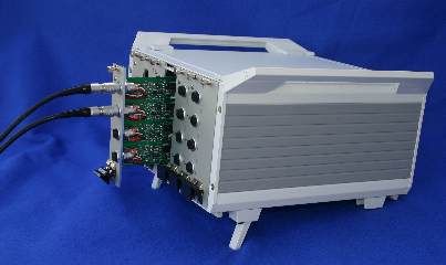
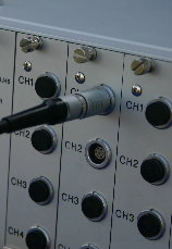
Connectors
The interface cards use CNT bayonet fitting 7 way connectors with automatic pin alignment. The sockets can only be released by pressing the release catch making them ideal for long term stand-alone operation even under the action of high vibration.
Once the sensor inputs cables are terminated with the sockets they can be fastened to the instrument and removed very quickly ensuring fast upgrade and maintenance. Figures 9 and 10 show cables terminated to the instrument.
Once the sensor inputs cables are terminated with the sockets they can be fastened to the instrument and removed very quickly ensuring fast upgrade and maintenance. Figures 9 and 10 show cables terminated to the instrument.
Figure 8 shows the gas discharge and transorb lightening protection fitted to an input card.
Fig 8
Fig 9

L
N
Gp (Isolated Ground Plane)
Instrument Case
Analogue Input Card
Fig 11
Input Connector
Isolated Ground Plane
Opto-Isolator
1000V Isolation
Provided by opto-isolator
Provided by opto-
Fig 12
Opto-isolation
The analogue input boards is electrically in two halves but physically a single board. The two halves are electrically isolated using an opto-coupler which provides the high voltage insulation. Figures 11 & 12 show how the opto-isolation is connected to the ground plane and used within the instrument.
The input stage of the analogue card provides an individual isolated ground plane and it is to this ground plane that the input signals and screens are physically connected. No input signal passes directly into the instrument and all inputs are individually isolated.
The power supply needs to be Earthed at all times when utilising the gas discharge/transorb lightening protection.