|
Connecting Mains Electrical Power |
|
Step 1) Ensure that the mains power supply is switched off before connecting mains power cable to the instrumentation. |
|
|
|
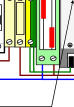
Step 2) Connect the Live and Neutral power cables to the isolator switch. Brown (Live) Blue (Neutral) |
|
|
|
Step 3) Power On the Instrumentation and the Green status LED on the 24V DC power supply and logger unit and also the Red status LED on the modem will be illuminated. |
|
Connecting Battery Backup To Instruments |
|
|

|
|
|
Power Supply 12-20 V DC @ 3W |
|
No of Channels 8 Diff or 16 Diff depending upon specified model |
|
Data Loggers 2 Independently Configurable Recorders |
|
Logger Sample Rate General Logger - User Defined - 1 sec to 3600 Sec (Hour) |
|
Event Logger 0.1,1,10,60,600,3600 Sec |
|
Data Reports Automatic E-mail Reports configurable for |
|
Hourly, Dairly, Weekly, Monthly, No Records |
|
FTP Server for dial-in data download |
|
File Format Comma Separate Variable CSV |
|
Modem Support GSM Mobile Phone with data link, GSM Modem, |
|
Hayes compatible Modem |
|
Sensor Inputs RTD, Thermocouples, Voltage, Current, Restistance, |
|
Strain Gauges, Load Cells, Current Loop 4-20 mA |
|
and 0-20 mA |
|
Status Messages Isalive (Dated Report) OnBootup (when unit restarts) |
|
Network Ports Ethernet Port, RS232 Modem Port, Internet Ready |
|
ADC Resolution 24 Bit ADC - 16 Million Levels |
|
Input Range 0,25mv, 50mV, 100mV, 500mV,1V, 5V |
|
Sample Rates 1 to 100 Hz for 8 channel systems |
|
1 to 50 Hz for 16 channel systems |
|
WebServer Systems Configuration and Data Viewing |
|
DATA LOGGER |
|
This System must be Earthed |
|
Tide Level Monitoring Instrumentation Manual |
|
This system uses mains power. Only suitably qualified personnel should make any changes to the system when the instrumentation is powered from the mains and the enclosure is open. |