|
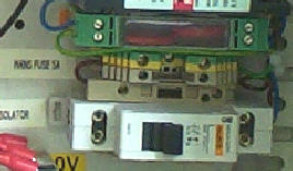
Main Instrumentation |

|
Transient Protection |
|
Mains Isolator |
|
Fig 6 |
|
Instrumentation Earth Point |
|
The instrumentation has a central earth point and the external earth must be connected here. It is not recommended to use the system without the earth being connected. The Earth point utilises the industry standard Green/Yellow DIN Earth Tag. |
|
Mains Isolator Switch |
|
Wiring Schematic & Component Layout |
|
Current Loop Interface |
|
Level Sensor Power |
|
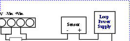
The acoustic level sensor uses a powered current loop to obtain power and and pass signal information to the logger. As shown in Figure 7 the height signal in the form of the current loop is converted into voltage across the sense resistor before being recorded by the logger. |
|
Fig 7 |
|
Pin-outs looking into logger Input |
|
Figure 8 - General System Wiring Schematic |
|
Sensor Deployment |
|
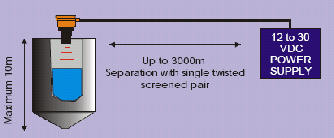
The acoustic sensor can be deployed up to 3 Km away from the logger unit when using a 4-20 mA current loop to pass signals to the logger for recording purposes. |
|
3° max |
|
0.88 m |
|
D |
|
D Min = 0.3 m |
|
To Logger |
|
Fig 9 |
|
Fig 10 |