clipboard-005.jpg

Modem to Logger Interface

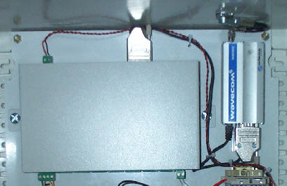
The Wavecom GSM modem connects to the NDACS logger by the 9 pin D connector located on the rear of the logger unit to the 15 pin D connector mounted on the base of the Wavecom Modem.

Remote Antenna Installation

A low profile SMA connector on top of the modem connects the remote antenna mounted on top of the IP67 Polycarbonate enclosure to the modem unit. The remote antenna mount passes through the hole cut into the top of the enclosure.

Mounting External Antenna

The external rubber antenna screws tightly onto the base unit once the remote antenna stub is passed through the Poly-carbonate enclosure through the hole provide above the modem. Ensure that the antenna is tightly attached so that no water can ingress around the mounting

Keynes Controls recommends fitting silicon grease around the external antenna mount above the modem at the top of the enclosure.

The following notes detail setting the logger unit to process and display the tide information. Process options are available for real-time and averaged results. The real-time tide level results should be able to show wave as well as tide information.

System Setup

The NDACS logger has been configured to accept an input signal from a level sensor in the range of 1 to 8 m representing a signal of 4 - 20 mA loop signal from the water level sensor.

The 4 - 20 mA current loop gives an input to the logger of 0.4 to 2V across a 100 Ohm precision sense resistor. It is not possible to know in advance how the level sensor will be deployed or how the results are to be shown to an operator

What is going to be demonstrated by example is how the logger can be configured to allow representation of the input signal to show results in easily understandable format.

Software Configuration

Process options

The Tide level sensor can be used on 2 process options, Scaled Current (Averaged) and Scaled Current. The Scaled Current option gives real-time results. The Scaled Current (Averaged) gives the average value of a defined time period. The (Averaged) option is used to remove the spray and wave effects on the tide information.

Scaled Current - Averaged

This process option averages the results from the input sensor over a defined period typically 1 minute. When used with the level sensor the wave effects and water spray are removed.

A = Sense Resistor (typically 100 Ohm)
B = 0.004 (4 mA) C=0.02 (20 mA)
D= Range for 4 mA input

E= Range for 20 mA input
F = Averaging Period (seconds)