Real-time Frequency Display
All of the VibWire-108 models contain a 5 digit 7 segment display and this can be used to display the instantaneous frequency from any of the vibrating wire sensor inputs.
Sensors can be deployed a considerable distance from the sensor interface and may well be have been embedded into a structure. To ensure that the sensors are operating correctly simply observe the sensor operating frequency and then confirm the result is within the operating range as specified by the manufacturer.
When operating in a real-time mode the instrument frequency display responds instantly to effects upon the sensor.
The VibWire-108 can display Period, Percentage of range and Frequency in Hz, however results transmitted across the different networks are only in Frequency (Hz)
To use the VibWire-108 as a real-time frequency display follow the instructions below:
Assigning Real-time Frequency Display
To activate the real-time frequency display
The “Basic” menu item is the first menu item available after the instrument is powered on.
2. Select “Menu In” button
The Display above shows the option required to place Channel 0 for real-time frequency output
the other options available are:
“Analg Seria C0d C1d C2d C3d C4d C5d C6d C7d” C0d = Channel 0 ........ C7d = Channel 7
Once the “C0d” option is selected then the “Menu Out” key has to be pressed to confirm this option.
Loud Speaker
On/Off Switch
On/Off Switch
Speaker
Loud Speaker
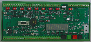
Frequency Display
All of the VW-108 range of instruments are supplied with an internal ceramic speaker. The speaker can be activated and the sensor ping and resultant echo can be heard.
The speaker used in collaboration of the frequency display should enable nearly all sensors to be tested no matter their location using only the VW-108 interface unit.
The speaker tone contains the sensor echo as well as the instrument ping.
If a low frequency hum is heard then noise pick can be a problem. If the gauge cabling is routed near a transformer, electric motor, high current power cables, etc, then relocate or reorient the gauge for minimum pickup. Ensure that only shielded cable is used and that the shielding is terminated at a single point to prevent capacitive pickup.
Sensor problems
Should a clean ping not be heard when the vibrating wire strain gauge is being sampled by the instrument the following guide should help.
1) If there is only random noise on the speaker for the defined channel then check the wiring and circuit resistance. The most common error is an open circuit. Locate and fix the broken cable.
2) If a ping can be heard but it is faint then the sensor cable may be too long, or a to high cable resistance is being used causing degradation of the signal amplitude. Finally the gauge sensitivity may be to low.
3) If the ping is not a pure tone then the gauge is possibly faulty. The gauge may have become damaged during installation.