Local Cable Free Data Transmission Configuration
The VibWire-108-TRN24 contains a local 2.4 GHz spread spectrum transceiver capable of providing local cable free operations over a range of 750m - 1 Km using small dipole antennas to several kilometres with a directional antenna. All of the control operations for the transceiver are User Defined and are detailed below.
Fig 17 - VibWire-108 with Zigby interface
Local Operation - Under 500 m to Gateway
The VibWire-108 mounted in a plastic or GRPS IP65 enclosure as shown in Figure 17A with the antenna mounted in effective line of site to the data logger or Keynes Gateway systems will operate to a range of approximately 500m. Depending upon conditions at the deployment site it is possible to get greater distances than 500 m so long as there is little interference or no obstructions to the signal path.
Configuring the VibWire-108 for data transmission
The is essentially two separate configuration operations to be undertaken when using the VibWire-108 for local cable free data transmission and they are:
1) Sensor Polling rate.
2) Data Transmission rate.
There is a always a trade off between sensor sampling rate, data transmission rate and power supply requirements. The faster the sensor sample rate and the greater the data transmission then the greater the power that is required to drive the instrument.
At low sample rates such as 1 record from each of the eight channels per day then 12V DC supply made up from AA cells will run the instrument for several years.
For many applications a small 12V rechargeable with a 4.8W solar panel will run the instrument indefinitely.
Setting Data Transmission Rates
To activate the real-time frequency display
1. Starting at
2. Use the Up & Down Keys to select the
“Tra.Int” option
The other options that will be displayed while the Up and Down keys are:
“Disp Perod ID Tra Tra.int Ch0.LA Ch0.RA .... ”
Once the “Tra.int” option is selected press the “Menu In” key to access the transmission rate options.
Options are “5S 60S 360S 600 1HR 6HR 24HR”
4. Once the desired transmission rate is set select the “Menu Out” key to confirm the option.
Note the transmission rate can be overwritten during the data logging operation to the SQL database.
Setting Sensor Polling Rate
To activate the real-time frequency display
1. Starting at
2. Use the Up & Down Keys to select the
“Perod” option
The other options that will be displayed while the Up
and Down keys are pressed are:
“Disp Perod ID Tra Tra.int Ch0.LA Ch0.RA .... ”
Once the “Period” option is selected press the “Menu In” key to access the polling rate options.
Options are “1S 5S 15S 1HR 6HR 24HR”
4. Once the polling rate is set select the “Menu Out” key to confirm the option.
Press the “Menu Out” key several times to get back to the BASIC option.
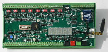
Figure 17 above shows the VibWire-108-TRN24 with a simple 3 db helical antenna attached that is suitable for local operations only.
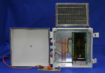
Fig 17A Complete 8 channel vibrating wire sensor system