pp42c4067c.jpg
pp42c4067c.jpg
12V DC
12V DC
SDI-12 Serial Network Connection
The SDI-12 multi-drop network requires only 1 wire to be connected between instruments for the communication of data.  This ensures that the installation and use of the SDI-12 network very simple operation. The SDI-12 network has a limited range but is ideally suited when connecting instruments together within an enclosure or when systems are deployed locally.
Each instrument can have its own independent power supply but must have the two dedicated network wires connected as shown above in Fig 7. A unique instrument identifier has to configured in order to access data from a dedicated instrument. Any data logger supporting the SDI-12 network can obtain information from the VibWire-108-SDI12.
Ensure that a good Earth connection is made and fitted to each instrument in order that the lightening protection discharge tubes will operate.

SDI-12 data on pin 4

All the Gnd terminations are
Starting SDI-12 Network Communications


To activate the analogue output channels on the VibWire-108.   

1. Starting at     


2.    Select “Menu In”  button

3.    Use the Up & Down Keys to select the option “Seral

Analg C0d C1d C2d C3d C4d C5d C6d C7d” are the other options available

Once the “Seral” output is selected the “Menu Out” key has to be pressed to confirm this option.

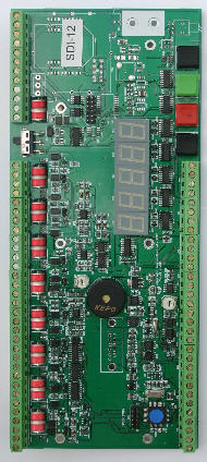
4.      The VW-108 will return to the display


 and now the SDI-12/RS-485 port for  the instrument is now activated.
Instrument Identifier

Each instrument deployed on the SDI-12 multi-drop network must have a unique instrument identifier set in order to  identify specific instrument on the network. For the SDI-12 network this identifier is 0-9.

See  for details on setting the ID number.